• Dear visitors,

    The email issue has been finally solved.
    Thank you for your patience and happy browsing.

    Team ACM.

W.I.P. Bedford Loops

Willy Wale

Member
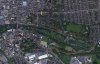
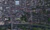
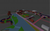
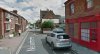
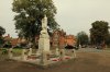
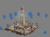
Time to stop spamming other people's threads and start putting things in one place. I've taken on the possibly too ambitious task of creating a circuit for Assetto Corsa around Bedford, UK.

preview.png


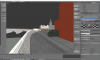
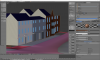
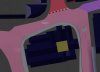
To do this I am teaching myself Blender and modding as I go. I'll post my progress, mistakes, and learnings here.

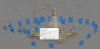
Please don't expect rapid progress, I started in Dec '16 and have barely enough to justify a WIP thread. I keep starting again as I learn better methods and workflow.

WW
 

Willy Wale

Member
Layout

I decided on a route around the centre of Bedford that is 2.7 miles (4.3km) long. As I started work I realised the enormity of the task so also devised a smaller 1.1 mile (1.8km) route to do first to bring a goal closer to my reach.

GP layout - 2.7 miles

GP Route.jpg

This route starts in a street of terraced houses then races along the river and onto a fast road that loops back to the town and over the bridge, back along the river, and some small tight streets to finish the lap.

Indy layout - 1.1 miles

Indy Route.jpg

Same start to avoid more spawn points but the route stays entirely in the town centre including a loop around St. Paul's.
 
Last edited:

Willy Wale

Member
To make this project I'm refering to:

OS Master Map Data
OS Landranger Maps
Environment Agency LIDAR
Google Streetview
Reference photos that I've taken
Photogrammetry from ref photos

I'll post a bit about each as I go.
 
Last edited:

Mr Whippy

Active Member
Looks like an interesting project... you've kept it pretty small which is a good idea for any city course :D

My main question is where are the pits going to be? Pits are usually as long, or longer than the route around them, and need a fairly decent amount of space too.

My main 'eek' moment for you right now is a lack of any solid Z reference.

Everything in a city moves around in Z and you have so many assets that all need to tie back to a consistent Z point.
Ie, if you tweak the road up a bit, then the buildings need to move up a bit too, otherwise the pavement between will be slanted.

A core part of making any city track (imo) is working on a Z surface that you use as a trusted Z position (just like you use top-down vector outlines for the map as trusted XY positions) to work towards.

How you do that is up to you, but I've found using as low a density mesh as possible which is smoothed/sub-divided as you set the z heights of the control vertices is the best approach.

Even if this means just doing a spline (with real heights for the spline knots) sweep along the main route, and then using that as your Z look up.


I'll have to post my Leeds Loops WIP here at ACM.

It might be useful for you to see how I've gone about a very similar concept so far. UK city courses FTW!!11!!

http://www.assettocorsa.net/forum/index.php?threads/leeds-loops-wip.32352/

It's there, but I've no idea how to get it here :D

Any mods want to do me a favour :D :D
 

Willy Wale

Member
My main question is where are the pits going to be? Pits are usually as long, or longer than the route around them, and need a fairly decent amount of space too.
The pits run along Newnham Street/Rothsay Place :) Which is just north of the start/finish 'straight', but on the left of the image below.

2017-07-16.JPG

I do have an issue with the pit exit at the moment. Cars will join the circuit on the outside of a corner which isn't ideal. Main straight on the left, pit exit at the top, all traffic heading towards the bottom of the image. I'll either reverse the roundabout direction for the pit exit or widen the road at the bottom and add a pit wall so the cars are all parallel. But I wanted to avoid straying too far from the real layout of the roads.

2017-07-16b.JPG

My main 'eek' moment for you right now is a lack of any solid Z reference.
I have a series of Z points that I have put into the model. The OS master map has a fair few point heights marked and where the road crosses a contour line on the Landranger map I have grabbed those as well.

Because of the spacing I will probably have some tweaking to do later but centimetres rather than metres. My intention is to leave the buildings roof as datum and bring the bottom up to the pavement level. None of my buildings are very detailed yet. They are there as a visual reference so I can slow down in time for the corners when testing.

2017-07-16c.JPG

I am attracted by your method to make a reference Z surface. Just looked through the Leeds Loops posts. I'll give it some thought.

WW
 

Mr Whippy

Active Member
The point heights on OS are very useful because they are really solid reference points for engineers, so it's great you've got them.
I've often found they contradict with other sources, but I know the OS data is 100% spot on so if it's what you've got you know it's trustworthy as a full data-set (ie, it's not right in one place but wrong in another, or has drift, etc, like GPS might have etc)


I'd definitely work on a separate model that works for figuring out heights using just the data you have and then smooths in between if you can.
You can then iteratively improve it, add more height points to it, and things just start to come together like a jigsaw.


Alternatively given you're making a UK track, I can do what I did for ir Sindaco and for my own Leeds course, and send mesh/textures over to use as reference?

You can never have too many UK city tracks on the boil :D
 

Mr Whippy

Active Member
Oh and the pits look well set out.

Have you got a rough top down map of the layout and any chicanes etc you want in there? Even roughly?

It's fun even at this stage to see what you have in mind before you get around to that stage of the build :)


I fancied doing a kinda Zone Industrielle type thing from NFS5, and having a more industrial area of a city as the roads are always loads wider in big industrial zones, so loads of scope for more interesting layouts.
 

Willy Wale

Member
Alternatively given you're making a UK track, I can do what I did for ir Sindaco and for my own Leeds course, and send mesh/textures over to use as reference?
If you have the time that would be great.

Have you got a rough top down map of the layout and any chicanes etc you want in there? Even roughly?

It's fun even at this stage to see what you have in mind before you get around to that stage of the build :)
Yep, pink is track, salmon/red are side roads, and the lilac strip is pits.

2017-07-16d.JPG

Actually, I'm not going to add chicanes as there are a couple of existing ones.

At the beginning of the pit lane the Castle pub juts out into the road and just before the pit entry near the end of the lap the road narrows to less than 5m.

2017-07-16e.JPG 2017-07-16f.JPG
 

Mr Whippy

Active Member
I'll try find the time to capture/generate the stuff needed for you.

If I just stick to the short track for now? It'll make the job about 4x easier for now.


Cheers

Dave
 

Willy Wale

Member
I've been working on the road surface. There's a lot of camber to take care of. Alongside that, for variety, I've finally bought a licence for Agisoft's Photoscan. There are a few features around the lap that will need some detail.

The war memorial stands at the end of the second straight. Cars will come from the direction of the red taxi and then turn right on the short course or turn left for the longer course. I plan to set a track camera roughly where I took this photo from, but higher in Z.
WM Carmera View.JPG

I expected Photoscan to struggle with the small bollards around the edge of the base but it seems to have sorted it. I was going to upload the detailed image but it's going to take a while.

2017-08-26 Waiting.JPG

While I'm waiting I've just watched a youtube video where a guy took 1000 pictures with a drone. I've only got 227. Adventures in photogrametry :)

WW
 

Willy Wale

Member
Tries to create the dense point cloud at the high setting (one down from highest)... After twelve hours my PC crashed. At the medium setting it only took 15 minutes. I now need to look at masking to clean up the resultant geometry. Also, needed to be more comprehensive with the photos. Too many holes.

2017-08-27.JPG
 

Willy Wale

Member
If you're trying to learn something new, there's normally an easy tutorial to follow to get going. Starting with a war memorial probably isn't the best idea.

How about a painted wooden post?

2017-09 Wooden Post photo.jpg 2017-09-24 Post-dense cloud.JPG 2017-09-26 Textured post in Blender.JPG

Yes, photogrammetry is overkill for a simple shape like this, but, I got to go through the workflow from beginning to end. I learned:

  • You need a surprising number of photos even for a cuboid. On my first attempt I took 17 photos but the model that photoscan pulled together was not good. On the second attempt I took 64
  • Photoscan makes everything tiny despite re-creating the model from known camera data, I don't think the standard edition of the software allows scaling of the model. Pro version does.
  • Experimentation with the camera optimisation settings are required. I don't have a definitive workflow yet.
In spite of the simplicity, I have a disproportionate level of satisfaction to get it into Blender. Now back to the war memorial(s), post boxes, bollards, bins...

WW
 

luchian

Administrator
Staff member
The result looks as realistic as it could ever be. Sure, it was simple geometry in this case but for those complex shapes it is worth it. Not only for the modelling time but alsonfor texturing (..especially if you lack some skills in this area like me :D).

Sent from my phone using Tapatalk
 

Willy Wale

Member
The result looks as realistic as it could ever be. Sure, it was simple geometry in this case but for those complex shapes it is worth it. Not only for the modelling time but alsonfor texturing (..especially if you lack some skills in this area like me :D).

Sent from my phone using Tapatalk
Absolutely. The texturing is the biggest advantage in my mind. The software lines up all the photos for you and wraps them round the simplified geometry. I'm sure the mesh that photoscan generates can be used to make the normal map too.
 

luchian

Administrator
Staff member
The one downside is that the uv mapping is .. very customized :D. That might be a problem if one would wish to compact textures maybe. Anyhoo.. in the grand scheme, is yet another posibility a modder has. That is good news in my book.

Sent from my phone using Tapatalk
 

Willy Wale

Member
The one downside is that the uv mapping is .. very customized :D
That stumped me for a while, but if you UV unwrap the simplified geometry in Blender/Max then import; Photoscan respects that and maps the texture accordingly.

Edit: Image added
2017-09 Wood-Post-Tex.JPG


Also the geometry you import can be a section of the model photoscan has built. For the post I only imported the geometry shown in the last picture, the texture map is created for the target geometry based (I think) on the nearest surface of the photoscan mesh.
 
Last edited:
Top