TUTORIAL Build your FIRST track - BASIC GUIDE
- Thread starter luchian
- Start date
Hey guys! Hope you're all alright! ")
I have for a long time had the urge to make some tracks for AC and today I found this thread and felt that I have to get my thumb out of my ass!
I got some very nice support from Luchian earlier today, thank you very much for your support, it is very much appriciated!
I am new to Blender, fired it up for the first time today and I havn't really gotten that far, and I need your help.
Thing is I don't know how to scale.
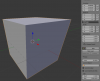
I know that the track in the picture below is 10 m is width at all times and it is a total of 2400 m in lenght.
Can someone that knows how to work Blender tell me if it's possible to tell Blender that the distance between these two blue lines (pictured below) is exactly 50 meters, and Blender will then calculate and scale the rest of the track?

If not, can someone that has a minute over help me with a step by step, stupified, guide for dummies on how I will scale this correctly? How I make a setting for distance to be meters?
I appologies for the probably quite stupid question
I have for a long time had the urge to make some tracks for AC and today I found this thread and felt that I have to get my thumb out of my ass!
I got some very nice support from Luchian earlier today, thank you very much for your support, it is very much appriciated!
I am new to Blender, fired it up for the first time today and I havn't really gotten that far, and I need your help.
Thing is I don't know how to scale.
I know that the track in the picture below is 10 m is width at all times and it is a total of 2400 m in lenght.
Can someone that knows how to work Blender tell me if it's possible to tell Blender that the distance between these two blue lines (pictured below) is exactly 50 meters, and Blender will then calculate and scale the rest of the track?
If not, can someone that has a minute over help me with a step by step, stupified, guide for dummies on how I will scale this correctly? How I make a setting for distance to be meters?
I appologies for the probably quite stupid question
Until I remember how to measure the actual bezier curve, this is what I would do .
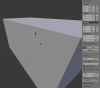
Go into top view (press 7 on the keypad)
Create a cube and modify it to fit between the blue lines
Look into the right panel and see its dimensions
Let's suppose it has 1.2 m. That means that your scale factor is 50/1.2=41.66
Now select the bezier curve and enter this scale factor manually in the right block (x, y, z)

Then CTRL+A > Apply Scale.
Done.
.Go into top view (press 7 on the keypad)
Create a cube and modify it to fit between the blue lines
Look into the right panel and see its dimensions
Let's suppose it has 1.2 m. That means that your scale factor is 50/1.2=41.66
Now select the bezier curve and enter this scale factor manually in the right block (x, y, z)
Then CTRL+A > Apply Scale.
Done.
marius van wyk
New Member
wow Lucian. I am new here. Your tutorial on building a track is amazing. step by step. well done mate. cheers
sunfffd
New Member
Hey guys whats up! Amazing info you got here!
Just got AC last week and landed on this forum because I wanted to build a local mountain route!
Was wondering does AC supports a endpoint to endpoint track? like a rally stage or something? The mountain route I wanted to build is a pretty narrow two-way road. Else I will need to think about how to make it a loop.
Hi @sunfffd , thank you and welcome
Absolutely, AC does support A-to-B tracks.
Small differences in the spawn points naming (..should add this to the guide):
AC_AB_START_L, AC_AB_START_R
AC_AB_FINISH_L, AC_AB_FINISH_R
Keep the same naming for pit spawn points
Keep the same naming for hotlap start spawn point
No starting grid.
So fire-up the 3d package and start building
Last edited:
sunfffd
New Member
@luchian awesome!
I'm thinking to first import a terrain from Google Earth to SketchUp then to Blender as a base route reference,
and work the textures and details from there. Do you think it will work?
Video:
Updates: I exported the collada file from Sketch, after importing to Blender, how can I make sure the model and mesh are in scale true to real world?
Last edited:
Yes, it will work for sure. There are different methods to import terrain into Blender (or other 3D package). You can see another method described HERE, by our expert user @liquido .
And soon enough, an almost automatic tool - HERE.
But until then, go ahead with your method, it will give a decent result, no doubt.
Good luck, keep us posted.
And soon enough, an almost automatic tool - HERE
.But until then, go ahead with your method, it will give a decent result, no doubt.
Good luck, keep us posted
.liquido
Active Member
can you upload a KML file of your route?Hey guys whats up! Amazing info you got here!
Just got AC last week and landed on this forum because I wanted to build a local mountain route!
Was wondering does AC supports a endpoint to endpoint track? like a rally stage or something? The mountain route I wanted to build is a pretty narrow two-way road. Else I will need to think about how to make it a loop.
It's a great chance to see if Zaxxon method is better than google earth terrain wich seems to be part of Race Track Builder.
Did you import any terrain of your project to Blender acctually ? in that case, can you show a capture with the wire frame visible?
The problem with zaxxon method is that you got a Bob's Track Builder File in the final and when you export to Blender you loose the Spline of the roads secctions and is really hard to work on a road without Spline and keep it smooth.
QuadCoreMax
Member
Hey all,
Thanks luchian for all the precious information.
I succeeded in porting my Racer tracks to AC. Now, I want to know more, so here the questions :
1. - What ID is used for collidable objects ?
2. - What if I want to use flying flags for my tracks, what shader is best ?
3.- What about the rest ( cameras, AI, crew...), what's the cleanest & quickest way to set them ?
---------------
Racer-Max
---------------
Hey @QuadCoreMax , welcome to the forums.
1/ AC_POBJECT_suffix
2/ you need to use ksFlags shader and they will autmatically be animated
3/ For cameras to work, you first need to define an AI line. See HERE.
Then for cameras, you should use the SDK Editor to define them, or use THIS quick&dirty solution (but will not have best results).
1/ AC_POBJECT_suffix
2/ you need to use ksFlags shader and they will autmatically be animated
3/ For cameras to work, you first need to define an AI line. See HERE.
Then for cameras, you should use the SDK Editor to define them, or use THIS quick&dirty solution (but will not have best results).
QuadCoreMax
Member
Great !
- Collidable Objects working
- AI path working
- Track Cameras working
I still struggle to understand what the groove is ?
+
How to generate automatically the map.png or track map from the Editor ?
- Collidable Objects working
- AI path working
- Track Cameras working
I still struggle to understand what the groove is ?
+
How to generate automatically the map.png or track map from the Editor ?
Technically, the groove, it's just another layer to be added over your tracks surface (like skid marks). Why ? The groove is used to actually give the track some "life", being dynamic with the advancement of the race. It's used to show the ideal line, which is darker due to being used more (hence more rubber particles on it).
If you would like to affect the way it behaves, you can do so by adjusting the parameters inside the groove.ini under \assettocorsa\content\tracks\yourtrack\data\
Parameters: There is a min value, a max value, and a stepping. Play with these and I'm sure you'll get what you are looking for. I would suggest not to cancel it all together, but maybe just to start with a higher min value.
NOTE: you can define multiple groove zones for your track if you wish - just define each behavior in the groove.ini.
For the second question, I am not sure there is a method to do that in the editor.. I *think there is a map.png generated automatically by the game it self (if none is present) but it will be according to the ideal line and not the track itself.
Best way (afaik) is to do an ortho render from above in your 3d software package.
If you would like to affect the way it behaves, you can do so by adjusting the parameters inside the groove.ini under \assettocorsa\content\tracks\yourtrack\data\
Parameters: There is a min value, a max value, and a stepping. Play with these and I'm sure you'll get what you are looking for. I would suggest not to cancel it all together, but maybe just to start with a higher min value
.NOTE: you can define multiple groove zones for your track if you wish - just define each behavior in the groove.ini.
For the second question, I am not sure there is a method to do that in the editor.. I *think there is a map.png generated automatically by the game it self (if none is present) but it will be according to the ideal line and not the track itself.
Best way (afaik) is to do an ortho render from above in your 3d software package.
QuadCoreMax
Member
I get little confused with the groove file, but I'm sure, I will, at some point, understand how it works.
As for map.png, it gets auto-generated by AC which is amazing. As you told, I have been doing an ortho projection screenshot & later edited in PS. Still, the track map wasn't aligned...
Very cool, everything seems fine now...
Time to get deeper with AC shaders & bring full realism to my tracks.
Thanks a lot